To improve comfort and convenience in the operation of lighting devices, a through switch is used: the wiring diagram visually reflects the principle of operation of the switching device. With it you can control the lighting of the room from any point. On the design features and installation rules for the product is described in detail in this article.
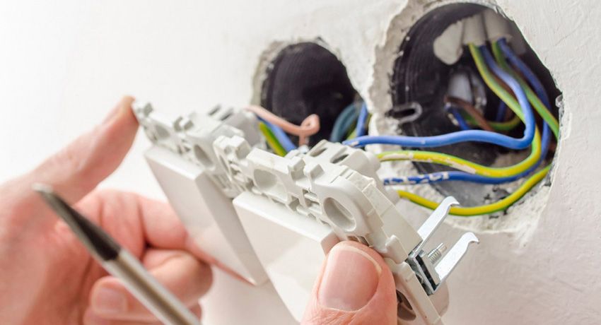
The design and principle of operation of the feed-through switch
Walk-through switches are designed to turn on and off the lighting from different ends of the room or the flight of stairs. This means that you can turn on the light, for example, when entering a room, and turn it off – in another part of it. Such a principle of action can significantly save energy.
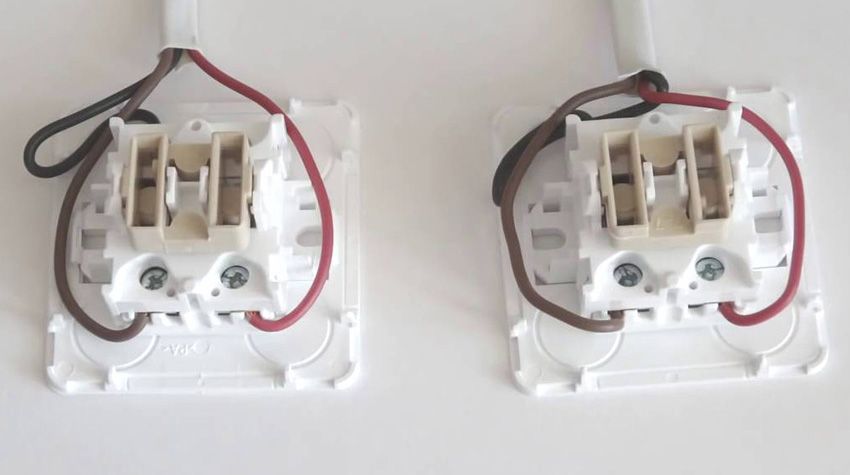
Passage switch in appearance does not differ from the usual. Its front movable panel also shows up and down arrows. A conventional switch has one input and one output. In contrast, the feedthrough device has one input and two outputs. This indicates that the current does not break, but is redirected to any of the outputs.
Despite the fact that experienced electricians will be able to determine by eye a switch, reliable manufacturers produce products with a double-pass, three-way or single circuit-breaker circuitry, which is located under the device body.
Determine that before the eyes is just a single passing device, it is also possible when inspecting the terminals with copper contacts. There should be three. In order to make sure that the terminals are not confused with each other, use a multimeter. The device should be put in the mode of sound signal and to ring its input and output. If when touching the contact the multimeter emits a signal, the contact is present in this place.
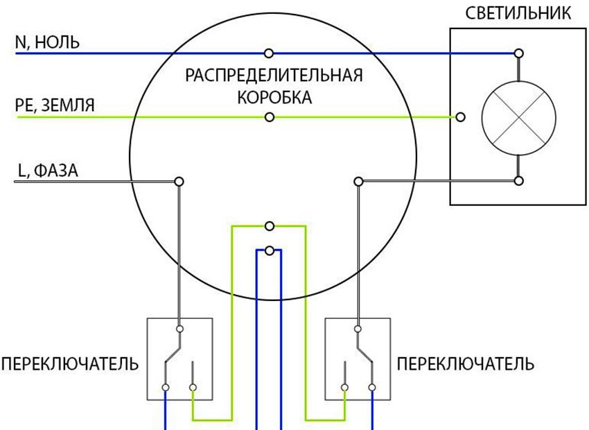
Another difference from a simple switch is the presence of a three-core switching device, and not a two-core switch, as usual. This is a kind of switch that redirects the voltage from one contact to another.
Pass-through switches are usually paired to control a single light source. Each is fed zero and phase. Changing the position of the switch toggles the circuit, which causes the light bulb to light up. When you turn off the first or second wiring switch, the phase opens, and the contact of the pair of switches is closed, and the light goes out. That is, when on both devices the keys are in the same position, the light turns on, turns off in different ones.
You can control the lighting not only from two places, but also from three or more. To do this, one or several cross-switches must be added to the general wiring diagram of the two-way pass switch.
Passing switches allow you to control the lighting of the room from two or more places, which is an indisputable convenience. This is especially valuable for houses on several floors with stairs. Here you can install the first switch on the first floor, and the next on the second, which will turn on the light at the bottom and turn off at the top.
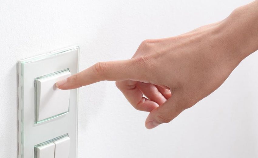
A good solution is to install one switch at the entrance to the bedroom, and the second one near the head of the bed, which will allow you to go in, turn on the lights, get ready for bed, lie down and turn off the lights. It is also advisable to install switches at the entrance to the house or apartment and at the end of the corridor.
Helpful advice! With the help of special motion sensors or a timer built into the switch, it is possible to organize automatic switching off of the light when leaving a certain place.
Pass-through switches have significant advantages over conventional devices:
- high reliability and safety of operation;
- instant shutdown of power supply of the room if necessary from any point;
- optimal energy consumption;
- low cost;
- simple installation that does not require the involvement of specialists;
- no complicated settings.
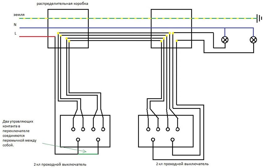
Despite the fact that at first glance, ordinary and pass switches have minor differences, their cost is significantly different. It is possible to buy the switch through passage in 1,5-2 times more expensively simple. Therefore, many craftsmen seek to manufacture a switching device independently.
To get a one-key switch through, you need to use the usual one-key and two-key devices of the same size and manufacturer.
Helpful advice! When purchasing a two-button-through switch, the circuit of which is applied to the device case, you should make sure that it has the ability to move the terminals in places in such a way as to ensure the opening and closing of the circuit independently of each other.
The process of reworking a simple switch in the gateway consists of the following steps:
- on the one-key overlay switch, the key is equipped with clips;
- gently squeezes the core of the switch;
- body clips are pressed on the internal mechanism of the switch;
- one of the terminals is removed from the socket;
- reinstall one contact against another;
- a rocker is installed on the contacts;
- body going back.
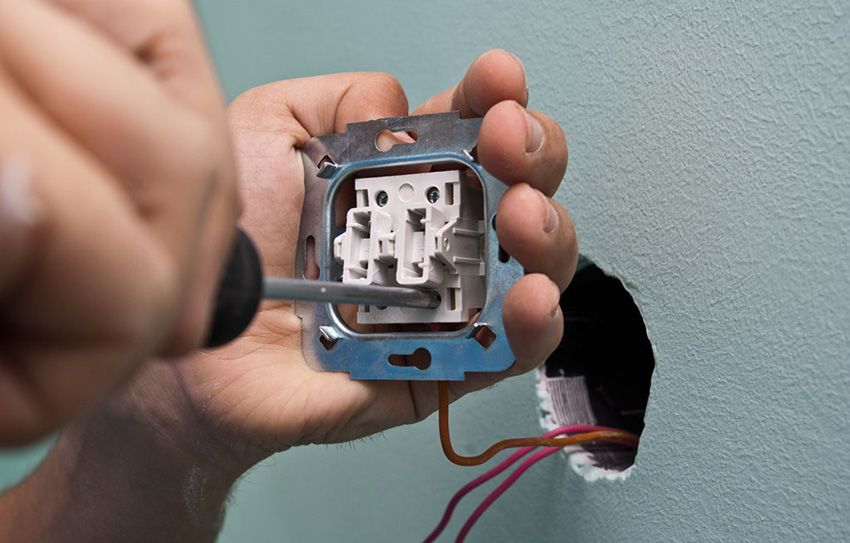
You can also assemble one switch of two simple ones. They should be positioned next to each other in such a way that, when acting on the upper part of the key, one is turned on, and on the lower part – the other. The keys should be connected to the plate, which is glued on top. It is imperative to install a jumper between two adjacent contacts.
Wiring diagram of the feed-through switch with 2 places
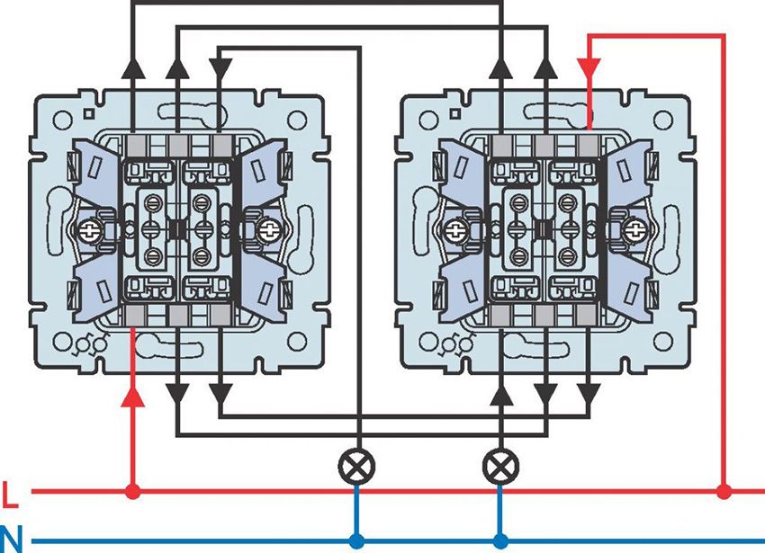
The circuit-breaker switch from two places is performed using two single-key devices that only work in pairs. Each of them has one contact at the entrance, and a couple at the exit.
Before connecting the switch to the switch, the wiring diagram visually displays all the steps, it is necessary to de-energize the room using the appropriate switch located in the control panel. Then it is necessary to additionally check the absence of voltage in all wires of the switch. To do this, use a special screwdriver.
Helpful advice! A similar test should be performed in the places where the switching devices are installed.
To perform the work you will need: flat, cross and indicator screwdrivers, knife, side cutters, level, tape measure and puncher. For the installation of switches and wiring in the walls of the room, it is necessary to make the corresponding openings and grooves according to the layout plan of the devices.
Important! It is not possible to install a loop switch in place of a simple switch.
It is necessary to lay the wires at a distance of at least 15 cm from the ceiling. They can be located not only in a hidden way, but also be laid in trays or boxes. Such installation allows fast repair work in case of cable damage. The ends of the wires must be inserted into the junction boxes, in which all connections are also made using contactors.
Installation procedure of switches through 2 points: wiring diagram
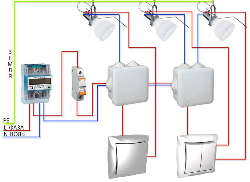
All actions for the installation of switching devices are carried out on the basis of the wiring diagram of 2 places of through switches, which can be found on the Internet. It differs from the installation of conventional switches, since there are three wires instead of the usual two. In this case, the two wires are used as a jumper between two switches located in different places of the room, and the third is used to feed the phase.
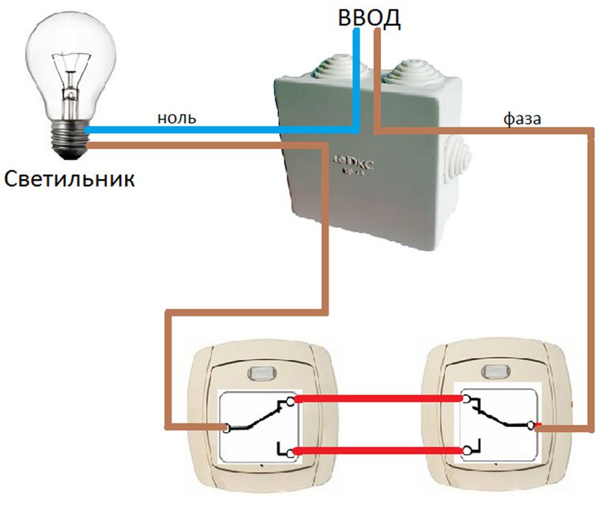
Five wires should fit the junction box: powered by a circuit breaker, three cables going to the switches, and a connecting wire directed to the lighting device. When building a connection circuit for a single-button-through switch, three-core cables are used. The wire “zero” and grounding are displayed directly on the light source. The brown wire of the phase, which supplies the current, passes through the switches according to the circuit and is output to the lighting lamp.
Helpful advice! To avoid problems with future wiring, it is recommended to use copper wires with a cross section of at least 2.5 mm2.
The switches are connected in the phase wire break, and the zero, passing the junction box, is directed to the lighting device. Passing the phase through the switch will ensure safety during repair and maintenance of the lamp.
Installing a loop switch consists of the following sequence of actions:
- Stripping the ends of the wires from the insulation;
- using the indicator, you must determine the phase wire;
- using twisting, the phase conductor should be connected to one of the wires on the first switch (white or red wires are used here);
- wire is connected between the zero terminals of the switches;
- connection of a separate wire of the second switch to the lamp;
- in the distribution box the wire from the luminaire is connected to the neutral wire;
Helpful advice! If twisting is done, they should be soldered and wrapped with tape.
If there is a need to control lighting devices from different places, then you should implement a connection circuit for a 3-point switch. This is true for high-rise buildings, large halls, and long corridors with several exits. To do this, in addition to two conventional through switches, a cross-over switch will be required. In such a switching device, there are not three, but four contacts: one pair of input and two output, which simultaneously switch. To do this, use a four-wire cable.
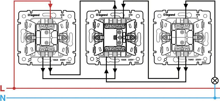
In the wiring diagram of the through switches with 3 places on the first and last point, conventional switches are used, between which a cross switch is installed.
Helpful advice! Since the disconnection in the junction box with each additional point is associated with a large number of wires, it is recommended to mark the wires.
The wiring diagram of the through switches from three places will look as follows:
- the lamp displays “zero” and grounding;
- connecting the phase to the input of the first pass-through switch;
- using wires, the output contacts of the first switch are connected to the input pair of terminals of the cross switch;
- connection of the output wires of the cross-switch with a pair of terminals at the output of the second pass-through switch;
- the wire from the second switch is fed to the lamp;
- the second wire, which goes from the lamp, comes to the junction box to “zero”.
The principle of operation and the installation of switching devices do not present significant difficulties. You must first study the wiring diagram and follow the recommendations of electrical safety rules, which will make it possible to carry out reliable and safe installation of devices, thereby ensuring convenient and comfortable control of lighting devices in the house.
How to connect a loop switch: video wiring diagram
